Ingeniería Mundial
  • Register

Smart Cadastral Tools for Real Estate Registration

Extensive Use of the INSPIRE GML Cadastral Parcel


The tools, systems and protocols as developed by the Spanish Directorate General for Cadastre are well accepted and widely used. A smart system of coordination between the Cadastre and the Property Rights Registry in Spain is now working and showing results. Agents working in the real estate market are now involved too.

In Spain, the Cadastre and the Property Rights Registry are two separate institutions with differentiated mandates and competences, both working in the domain of land administration. The Spanish Law 13/2015 implements an effective coordination of transactions executed by both institutions. Today the real estate transactions are performed with increased legal certainty. While georeferenced spatial information of parcels is incorporated into the Property Rights Registry, cadastral mapping forms the basis of the graphic representation used. The cadastral data is updated simultaneously with the Property Rights Register.

INSPIRE GML Format

The Cadastre, registries and notaries have worked together to design a technologically advanced model of institutional interaction for this coordination purpose. This model enables the application and use of georeferenced spatial information throughout all real estate transactions. The georeferencing of the parcels, expressed through the INSPIRE GML format of a cadastral parcel, is now widely used by all agents involved in property transactions in Spain. Information is continuously exchanged electronically between citizens, professionals and the various institutions involved. As a consequence, the Cadastre is aware and informed of any alterations to the real estate property recorded in a public deed or in any other object of registration, with a sufficient level of detail to carry out its unattended updating.

Figure 1, Cadastral certification with attached INSPIRE GML file.

Object description

The object present in real estate transactions must be identified at the start of each transaction. This must then be known and agreed upon by all stakeholders. The information derived from the cadastral spatial database is then processed in order to be correctly transcribed into the public transaction document and to be incorporated into the Property Rights Registry. The technical solution developed by the Directorate General for Cadastre allows the list of coordinates as present in the INSPIRE GML format to be linked with its graphic visualisation without the need for specialised GIS tools.

The cadastral cartography, and in particular the ‘descriptive cadastral and graphic certification’, has been chosen as the instrument to achieve the correct graphic description of the registered properties. This guarantees the coherence of the graphic information that is registered, ensures that there are no overlaps on neighbouring parcels or on neighbouring public land, and guarantees the graphic coordination with the Cadastre. The certified graphic information of the cadastral parcel is expressed in the INSPIRE GML cadastral parcel format (see Figure 1).

Figure 2, Generation of the INSPIRE GML file on the Cadastre’s website.

Representation of physical reality

In cases where the cadastral cartography does not sufficiently reflect the physical reality, procedures have been defined for updating the graphic data of the parcel involved through the use of alternative georeferenced graphic representations. These alternative representations are expressed again in the INSPIRE GML Cadastral Parcel format and can be generated from various computer applications. A simple internet search shows the plethora of tools available, appearing as free and open software tools, tools provided by professional institutions as well as tools from specialised commercial firms. Other options include free plug-ins for AutoCAD, QGIS or gvSIG as well as the tools presented on the Cadastre’s website (see Figure 2).

Validation

An alternative graphic representation must comply with certain technical conditions established in the relevant development resolutions. It must be represented in the cadastral cartography and the delimitation that already exists in the cadastral cartography must be respected. The accreditation of these conditions is verified by means of the ’validation service of alternative georeferenced graphical representations’ on the Cadastre’s website, (see Figure 3). This results in the ‘graphic validation report’ as shown in Figure 4.

Figure 3, Generation of the graphic validation report.

Latent demand

The key parts of the technical solution, the cadastral certification and the graphic validation report of the new, alternative georeferenced representation, can be obtained via a web service by citizens and professional users from the Cadastre’s website.

Over the course of 2016, more than seven million certificates and fifty thousand reports were issued, practically all of them electronically. Beyond the substitution effect of the face-to-face channel by the online channel, this shows the clear and ongoing emergence of a latent demand for cadastral information. Between the implementation of the Cadastre’s website in 2003 and today, the number of cadastral certificates issued has multiplied by seven, and last year saw an increase of more than 10 percent (see Figure 5). It must be emphasised that only 15 percent of certificates are obtained by private citizens. The other 85 percent are being directly obtained by professional users – the notaries, registrars and authorities that need them. These are obtained not only interactively, but also by utilising the electronic web-based services enabling automatic data exchange between the information systems.

Figure 4, Positive graphic validation report.

Authentic documents

The INSPIRE GML of the graphic situation of the cadastral parcel as certified by the Directorate General for Cadastre is embedded in the cadastral certification and the graphic validation report. The Directorate ensures the authenticity and integrity of its contents. This circumstance is achieved thanks to the fact that both products are electronic documents, signed using a secure 16-digit verification code. This code unequivocally identifies the document in the Directorate General for Cadastre’s catalogue. The exchange between the various stakeholders requires only the 16-digit barcodes (see Figure 6). This avoids the need to physically exchange computer files, allows the visualisation of the new representation without GIS tools and enables the automated capture of its contents, thus preventing possible transcription errors.

Figure 5, Evolution in the number of certificates issued. Red = on paper, Green = electronically.

Concluding remarks

The introduction of this system has enabled strong progress in the coordination between the Cadastre and the Property Rights Registry. The system contributes to standardising the internal processes of all the stakeholders involved in the real estate sector. Interoperability between stakeholders’ systems is enhanced and at the same time administrative procedures are simplified, costs are reduced and legal security is increased. Cadastral data has been incorporated and has been marked as coordinated in the Property Rights Registry, and the data related to delimitation, location and area is considered to be true for all legal purposes. This promotes transparency in real estate transactions by establishing an adequate procedure for generating spatial descriptions of real estate objects. This is principally based on cadastral cartography, and allows citizen participation by offering access for citizens to rectify and/or update the real estate object’s description.

Watch here a video showing how the various tools work.

6f6fd34081824fb8af3e7f03b0a44a8276246146
Figure 6, The graphic information is condensed into a 16-digit barcode.

www.gim-international.com - Viernes 10 de Noviembre del 2017

Autonomous 3D Modelling of Indoor Spaces

A Comparison of Mobile Indoor Scanning Methods


Mobile scanning can be an equally accurate yet more cost-effective solution than traditional terrestrial laser scanning done with tripods. To succeed, however, mobile scanners not only require a suitable combination of sensors, but also reliable and continuous knowledge about where the scanners are located and the direction in which they are pointing during scanning. There are multiple ways to achieve this, which has led to the development of various scientific and commercial solutions. This article compares several mobile scanning solutions for 3D modelling of indoor spaces and highlights their strengths and weaknesses.

In modern society, people tend to spend more time inside buildings than outdoors. Nevertheless, indoor spaces are – by far – less digitised than Earth’s surface. Modelling more indoor spaces from 3D measurements would satisfy many needs, and especially so if those measurements could be done rapidly, cost-effectively and accurately. Mobile scanning is a promising technology in this context.

Raw materials

Point clouds are the raw materials for 3D models. Mathematically, a point cloud is a set of points in a three-dimensional (3D) coordinate system. These points can be obtained from digital imagery or with laser scanning. In the case of imagery, prominent solutions use structure from motion (SfM) or its real-time variant, visual simultaneous localisation and mapping (SLAM). The structure, i.e. the geometry of indoor spaces, is triangulated from digital images visualising the same spots from different perspectives that can be acquired during motion. However, due to challenging lighting conditions and the scarceness of textures in indoor spaces, laser scanning appears to be the most promising approach so far.

Terrestrial laser scanning

Points are obtained from range measurements by the laser. The laser scanner emits a beam that is reflected with a revolving mirror to obtain a two-dimensional (2D) profile from the surroundings. If this 2D scanner is then simultaneously rotated on top of a tripod, it performs a 3D scan of the environment. Currently a single terrestrial laser scanning (TLS) scan is the most precise way of acquiring a dense point cloud of the surrounding environment. Due to occlusions, however, several scanning locations are needed – even in a relatively simple space – to achieve full coverage. It is possible to combine multiple tripod scans by using human-deployed scan targets in the field and software automation in the post-processing phase, or simply human intervention in the latter. Either way, this involves a considerable amount of manual labour.

Mobile scanning

Mobile scanning is faster than any scanning done using tripods and therefore provides more cost-effective solutions. There is a caveat, however: the range measurements cannot be used on their own. It is also necessary to know from where the measurements were taken, and pointing in which direction. If the scanner is sitting on top of a tripod, the pose of the scanner (its position and attitude) are usually known or can be determined easily. Scanning and moving at the same time, however, reduces point cloud accuracy because the scanner pose estimate is less accurate. After going mobile and having traded off some point cloud accuracy in favour of time savings, the challenge is how to reclaim some of this lost accuracy to reach the accuracy level that is required for indoor modelling.

Figure 1, A point cloud of Aalto University’s Startup Sauna.

Localisation

At the heart of a precise 3D point cloud is an accurate trajectory. Determining the pose of the scanner must be both continuous and reliable. Satellite signals typically do not reach inside buildings, which means that the trajectory must be obtained relatively, by correlating newly obtained measurements with those obtained earlier since the start of the scan. In other words, the question of the scanner’s location is answered by observing that the overlap of the data is coherent with itself. For example, when a wall is scanned twice, this data must be coherent with itself. This is the principle of SLAM.

Determining the pose requires a 3D Cartesian vector and a 3D angular vector. In other words there are six unknowns, or six degrees of freedom. These do not need to be solved at the same time. One trick to simplify the problem is to omit the height direction. Some methods use this and some do not; some use it as an initial estimate.

Comparison

There are thus multiple ways to localise the scanner. Not only are there different combinations of multi-sensor systems that can be assembled, but there is also a sandbox form of freedom in incorporating the algorithmic side, which deeply affects whether a certain approach is successful (please note that SLAM refers to a range of tools and methods, and not to any specific data processing algorithm).

Table 1, Introducing the evaluated methods. Capture time is walking speed (w), or measured in hours (h). N/A indicates that the 2D method could not reconstruct the 3D trajectory.

In the scientific paper on which this article is based (Comparison of the Selected State-Of-The-Art 3D Indoor Scanning and Point Cloud Generation Methods, see ‘Further Reading’), to evaluate the strengths and weaknesses of these different methods the authors analysed the performance of eight different scanning methods and compared them against a reference taken with a survey-grade TLS. Three different test sites were used, and the evaluated methods are listed in the table below.

Dimensions

When choosing the method to localise the scanner it is important to take into account the physical properties of the environment. The results of the comparison study show that estimating the scanner pose in two dimensions – as is done by the NavVis system – only produces less error in the 3D point cloud provided that the floor is flat. However, a wheeled platform such as NavVis is not navigable in all indoor spaces.

A scientific backpack from the University of Würzburg employs one horizontal 2D laser scanner to perform a more reliable localisation in two dimensions. Then the data from another scanner operating in 3D is used to calculate vertical corrections to recover the six degrees of freedom. Despite its potential, no commercial system uses this approach yet.

Table 2, Strengths and weaknesses of the evaluated methods.

Theoretically, localisation may begin in an even-lower dimension. The scientific device VILMA, from Aalto University, makes use of a theoretical solution to obtain the trajectory first in 1D, and then employs SLAM to expand the trajectory estimate to two, three and finally six degrees of freedom.

For versatile needs in staired or otherwise complex indoor environments, one valid commercial option is ZEB1 from GeoSLAM or one of its successors. Because the problem of determining the pose as a function of time is quite challenging, ZEB1 uses an inertial sensor to find a working estimate for the pose that can then be refined by correlating the measurement data.

Robustness

In addition to software development in mobile laser scanning, hardware is also improving. Localisation robustness is gained through multi-line scanners. In contrast to current 2D laser scanners that produce just one row of pixels, these multi-line scanners capture whole images, which increases geometrical constraints for a more accurate trajectory computation. For example, Kaarta’s Stencil solution employs a 16-row Velodyne for increased robustness. The product is a strong candidate for indoor 3D measuring.

Figure 2, Features with multiple length scales exist in indoor environments.

Sensor Fusion

Leica Pegasus:Backpack is a product available from Leica Geosystems. It mounts two Velodyne-16s to a backpack with a GNSS receiver for seamless indoor-outdoor positioning. However, it would seem that the multitude of sensors impacts somewhat on the overall performance, leaving Pegasus behind ZEB1 and Stencil in terms of point cloud accuracy.

Combining both worlds

Matterport is a product that lies between the two worlds of terrestrial scanning and mobile mapping. It combines a tripod-mounted depth camera system with cloud services that offer automated data post-processing. The scarcity of points in Figure 3 does not indicate that there is something amiss. On the contrary, the cloud is already thinned for 3D modelling purposes, and its accuracy – although less than that delivered by ZEB1 and Stencil – is undoubtedly adequate for various applications. On the downside, the 6-metre sensor range forces the user to do a lot of footwork.

dfbc55a61078388f621bca7981af00f56c17e170
Figure 3, Difference to the reference in height elevation.

Indoor challenges

Indoor spaces are challenging due to the fact that features span various length scales. For example, in the sketch in Figure 2, the width of the lamp leg has an entirely different length scale than the width of the room. The challenge is that the scanning method precision should be sufficient to capture the smallest sub-centimetre features while simultaneously being computationally able to track spaces spanning hundreds of metres. On the one hand, if the precision is not sufficient, the smaller features are incorporated into larger ones in the measurements, deforming their shapes. On the other, if the method attempts to capture spaces spanning large distances, there needs to be an efficient way to compress the data.

Results

There are multiple ways that may be used to differentiate the methods in terms of point cloud accuracy and precision. Differences can be sought between two point clouds A and B, between two similarly cut subsets of these point clouds, or between control points. In this comparison the authors have used the first two approaches. Figure 3 shows a subset of a point cloud, i.e. a ramp floor, captured in a car park. Note how the closest point accuracy behaves for different methods.

Conclusion

Relative positioning is mundane in geomatics for 3D point clouds obtained with a tripod and scan targets. With a continuously moving scanner, however, the situation is more complicated. Combining the best solutions from the current state of the art should provide an answer for the multitude of needs in 3D indoor modelling. Meanwhile, the best scanning accuracy is obtained from the wheeled NavVis platform, with Stencil being a good portable solution.

Application examples

3D point clouds of indoor environments offer a range of applications. During construction, the progress of the work can be followed digitally. Scanning updates keep track of completed phases and lead to automated updates for project schedules and delivery order dates, while also redefining critical paths so that resource reallocations may be suggested. Georeferenced verification of completed construction phases reveal possible problems and any need for revisions. In addition, construction permits issued by city officials become digitally manageable through building information modelling (BIM). The final checking of the built result can be digitally compared to the approved plans if the just constructed indoor spaces can be scanned. Digital archiving of the plans reduces public spending and improves archive usability. The as-built data is ready to be applied for renovation plans. Sustainability is achievable through thermal models of buildings that reveal the extent and source of heat losses.

Further Reading

Lehtola, V. V., Kaartinen, H., Nüchter, A., et al. (2017). Comparison of the Selected State-Of-The-Art 3D Indoor Scanning and Point Cloud Generation Methods. Remote Sensing9(8), 796.

www.gim-international.com - Viernes 10 de Noviembre del 2017

Emiratos Árabes Unidos crea un Ministerio de Inteligencia Artificial y planea un viaje a Marte

15084260100364Emiratos Árabes Unidos (EAU) ha creado un Ministerio de Inteligencia Artificial como parte de una reestructuración de gabinete en el país del Golfo. Omar bin Sultan al Olama, de 27 años, ha sido designado ministro estatal de Inteligencia Artificial, según indicó el primer ministro, Sheikh Mohammed bin Rashid Al Maktoum, en una serie de tuits en los que anunció los nuevos nombramientos. "La próxima ola mundial es la inteligencia artificial y queremos ser el país mejor preparado para ello", escribió.

El primer ministro agregó que el nuevo Gobierno refleja el objetivo de EAU fijado en "las capacidades del futuro, las ciencias y la tecnología".

El país también ha anunciado el nombramiento de dos nuevas ministras de Estado que trabajarán en la ciencia avanzada y la seguridad alimentaria. Sara al Amiri, de 30 años, será la ministra de Estado de Ciencias Avanzadas y "liderará la misión de EAU a Marte". Hace unos meses el país ya anunció que enviará una nave no tripulada al planeta rojo en 2022.

En 2016, el país creó dos ministerios, de Felicidad y de Tolerancia. EAU, una federación de siete emiratos, aglutina varias creencias y nacionalidades.

Por otro lado, en 2014, la Autoridad General de Asuntos Islámicos de EAU emitió una fatwa -pronunciamiento legal en el islam- prohibiendo el viaje de ida a Marte. La sentencia recogía que "este viaje supone un riesgo real, algo que no puede ser justificado por nuestra religión".

http://GIM-INTERNATIONAL.com - Jueves 26 de octubre del 2017

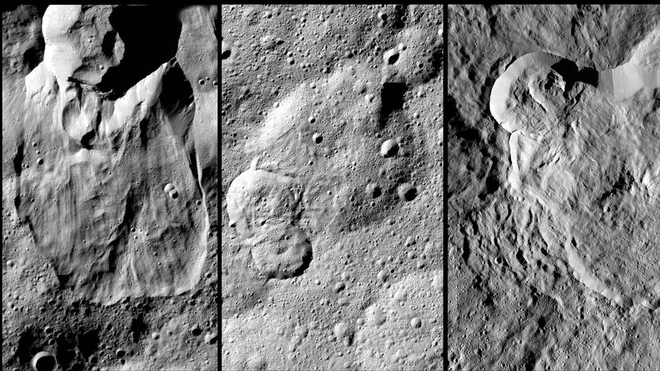
La NASA sobrevolará el planeta enano Ceres a baja altura con la nave 'Dawn'

15085158555479

La NASA ha autorizado una segunda extensión de la misión 'Dawn' en Ceres, el objeto más grande en el cinturón de asteroides entre Marte y Júpiter, para realizar sobrevuelos a baja altura. Durante esta extensión, la nave descenderá a altitudes más bajas que nunca antes en el planeta enano, que está en órbita desde marzo de 2015. La nave espacial continuará en Ceres para el resto de su investigación científica y permanecerá en una órbita estable indefinidamente cuando el combustible de hidrazina se haya agotado.

El equipo de vuelo Dawn está estudiando formas de maniobrar 'Dawn' en una nueva órbita elíptica, que puede llevar a la nave espacial a menos de 200 kilómetros de la superficie de Ceres en el mayor acercamiento (la Estación Espacial Internacional se mueve a 400 kilómetros de la Tierra). Previamente, la altitud más baja de 'Dawn' fue de 385 kilómetros.

Una prioridad de la segunda extensión de la misión Ceres es recopilar datos con el espectrómetro de rayos gamma y de neutrones de 'Dawn', que mide el número y la energía de los rayos gamma y los neutrones. Esta información es importante para comprender la composición de la capa superior de Ceres y la cantidad de hielo que contiene.

Estudio de los minerales

La nave espacial también tomará imágenes de luz visible de la geología de la superficie de Ceres con su cámara, así como las mediciones de la mineralogía de Ceres con su espectrómetro de mapeo visible e infrarrojo.

La misión extendida en Ceres también permite a 'Dawn' estar en órbita mientras el planeta enano atraviesa el perihelio, su acercamiento más cercano al Sol, que ocurrirá en abril de 2018. A mayor proximidad al Sol, más hielo en la superficie de Ceres puede convertirse en vapor de agua, que a su vez puede contribuir a la débil atmósfera transitoria detectada por el Observatorio Espacial Herschel de la Agencia Espacial Europea antes de la llegada de 'Dawn'. Sobre la base de los hallazgos de 'Dawn', el equipo ha formulado la hipótesis de que el vapor de agua puede producirse en parte a partir de partículas energéticas del Sol que interactúan con el hielo en la superficie de Ceres. Los científicos combinarán datos de observatorios terrestres con las observaciones de 'Dawn' para seguir estudiando estos fenómenos a medida que Ceres se acerque al perihelio.

El equipo de 'Dawn' está refinando sus planes para este próximo y último capítulo de la misión. Debido a su compromiso de proteger a Ceres de la contaminación terrestre, 'Dawn' no aterrizará ni se estrellará contra Ceres. En cambio, llevará a cabo toda la ciencia que pueda en su órbita final, donde permanecerá incluso después de que ya no pueda comunicarse con la Tierra. Los planificadores de la misión estiman que la nave espacial puede continuar operando hasta la segunda mitad de 2018.

'Dawn' es la única misión en la historia que orbita dos objetivos extraterrestres. Orbitó el asteroide gigante Vesta durante 14 meses entre 2011 y 2012, luego continuó en Ceres, donde ha estado en órbita desde marzo de 2015.

http://GIM-INTERNATIONAL.com - Jueves 26 de octubre del 2017

El ambicioso plan de Elon Musk para conquistar Marte con inmensos cohetes

El magnate Elon Musk, fundador y director ejecutivo de Space X, anunció recientemente su ambicioso plan para enviar humanos a Marte a partir del año 2024. Tal como adelantó en el 68º Congreso Internacional de Astronáutica, celebrado en Adelaida, Australia, Space X está trabajando intensamente en el diseño de un complejo sistema de naves de carga y de pasajeros para poder fundar una colonia permanente en Marte. El núcleo del proyecto está en las naves BFR, (del inglés «Big Fucking Rockets»), unos aparatos de 50 metros de largo capaces de transportar a 100 pasajeros y reutilizables como si de aviones comerciales se tratase.

Unos planes similares ya se anunciaron en el congreso del año pasado, celebrado en Guadalajara, México, donde Musk perfiló el papel de unas naves, llamadas ITS, en la tarea de establecer una ciudad de un millón de habitantes en Marte en el plazo de 50 a 100 años. Pero en esta ocasión, el magnate ha anunciado importantes modificaciones de su plan. La más destacable es reducir el tamaño de las naves y garantizarse que sean sostenibles económicamente.

«En la presentación del año pasado estábamos buscando una forma de poder pagar todo esto», dijo. «Probamos con varias ideas (...). Pero no resultaron. Ahora creemos que hemos dado con la forma».


¿Cuál es la receta? Pasa por usar naves ligeramente más pequeñas (y, por tanto, más baratas) que las ITS, las BFR, y usarlas en tareas que pueden darle rendimiento económico a la compañía. Estas son los vuelos de abastecimiento a la Estación Espacial Internacional o el lanzamiento de satélites. Esto implica en la práctica que la compañía tiene pensado dejar de usar sus actuales cohetes y su cápsula Dragon en un futuro no muy lejano.

100 pasajeros a Marte

Según la información presentada por Musk, las BFR medirían 106 metros de alto, 15 menos que el concepto del ITS anterior, y serían capaces de enviar 150 toneladas de peso a la órbita baja de la Tierra (mucho más que los cohetes más pesados actuales y que el Saturno V de la NASA, empleada en las misiones Apolo). La nave BFR, (de 48 metros de largo sin contar con los cohetes) podría transportar 100 tripulantes en un viaje a Marte, en un total de 40 camarotes.
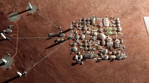
base marte kYhH 510x286abc 1
El objetivo es fundar una base permanente en Marte- SPACE X

Gracias al empuje de seis motores «Raptor», la nave podría supuestamente llegar a Marte después de un viaje de entre tres y seis meses. Los vehículos de desembarco aterrizarían vía «retropropulsión supersónica», con un método similar al usado por los Falcon 9 con éxito ya en 12 ocasiones. La propia nave BFR sería capaz de posarse con el empuje de sus dos motores principales.

El objetivo de Space X es convertir el sistema BFR en algo parecido al de una aerolínea, donde las naves pueden volar una y otra vez y hacer que la colonización de Marte sea rentable. «Realmente es una locura construir estos sofisticados cohetes y estrellarlos cada vez que volamos. Es absurdo», recalcó. «No puedo enfatizar lo suficiente lo profundo que es esto, y lo importante que es la reutilización».

El primer lanzamiento, en 2022

Tal como ha dicho, en la actualidad Space X está trabajando en serio en el desarrollo del sistema BFR. La compañía espera lanzar al menos dos naves no tripuladas a Marte en 2022. Su primera misión será confirmar la existencia de recursos y preparar las infraestructuras necesarias para futuras misiones.

De acuerdo con esto, Space X lanzaría dos naves de carga a Marte en 2024 para comenzar a construir una base y una planta de producción de combustible. Poco a poco, las naves BFR harían crecer la base, para finalmente lograr el objetivo a largo plazo de «terraformar Marte y hacer que sea un buen lugar donde vivir», en palabras de Musk.

Según el director ejecutivo de Space X, el sistema BFR sería idóneo también para preparar una base en la superficie de la Luna relativamente pronto. «Estamos en 2017, ya deberíamos tener una base lunar. ¿Qué demonios ocurre?», se preguntó el magnate. Además, las naves también podrían servir para mover pasajeros en la Tierra. Según aseguró, los viajes más largos podrían hacerse en menos media hora.

http://ABC.es - Lunes 03 de octubre del 2017

Conoce más sobre mi

conocemas

cuento


JUEGOS

Denuncias Públicas

denuncias

Consultor Internacional

consultor

Sociedad Colombiana de Topógrafos

sct

Ingeniería Mundial y Geomática

ingenieria

Cosas que no entiendo

cosas

Invitaciones

invitaciones

Mis Acciones en la SCI

SCI ACC

Recomendados del mes

recomendado

palilibrio